I had been thinking about a sail plane for a bit over a year. I’d looked at the Multiplex Easy Glider but always seemed to have something else to do or spend money on. After an unusual (for me) weekday morning at the flying field where one of the club members had a electric powered glider, I decided to pull the trigger.
I looked a little online and found most of my regular stops didn’t have the Easy Glider Pro in stock yet. I stumbled upon a hobby shop in San Diego and as I was planning a visit, I put it on my list of things to do.
 |
 |
The Easy Glider Pro comes boxed similar to the other Multiplex kits I’ve built. The few pieces were placed in the long narrow box with a couple of bags of small parts, the instructions and the large sheet of decals. It didn’t have the foam rack that the Gemini kit comes packed in, but it didn’t have the number and smaller surfaces the Gemini did, either. Upon inventorying the kit I found nothing damaged and nothing missing.
If you’ve built any other Multiplex Elapor foam kit before, you’ll see nothing unusual in the Easy Glider Electric. The same construction techniques of external control rod snakes and canopy clips are used with the Easy Glider Pro. There are a couple of things you’ll want to do before you start.
First, you’ll want to decide whether you plan to use the maroon and silver themed decals or paint. I have found that sanding the molding dimples off with very fine wet/dry sandpaper and a little water sprayed on surface produces a smooth surface for the paint. I’ve also found that sanding is not a good idea when the plan is to use the decals directly on the foam. The foam’s smooth surface is a better match for the decals and the dimples don’t seem to make a difference in performance. The point is you need to decide.
Second, map out the length of your servo wires coming from the wings mounting bays. I’ve found different brands have different lengths. You will need several extensions. The first is from the wing servo. The directions call for 60mm extending from the left wing root and 75mm from the right. Rather than make my own extensions to the exact fit, I used 24 inch extensions and cut a small cavity for the excess when the wings get pushed together. More on that later. The other extensions are required from the receiver to the servo connectors that mount in the fuselage on the lower surface of the wing opening. The length of these will be dependent on where you will mount the receiver. I wasn’t exactly sure so I used 12 inch extensions knowing I’d have enough length.
Last, you’ll need to consider your choice of motor and spinner combination. I chose a smaller brushless motor with a 4mm shaft. The recommended Multiplex spinner for the Cularis fits a 5mm shaft so that wasn’t going to work. Folks on the web suggested upping the shaft size with heat shrink tubing on the 4mm shaft. I didn’t get that to work so I went with an APC prop hub and blades with a 2 inch plastic spinner. Multiplex claims to have a 4mm spinner set coming as I write this, however.
Since I planned to paint the model, I took the time to sand off the dimples. When that was done, I followed the instructions to get started. By way of caution, if you are not using the Multiplex power system, you’ll want to fit your motor to the motor mount before gluing the fuselage together. Here is what I ended up doing.
I noticed that the mounting holes on my motor did not line up with those on the kit motor mount. My solution was to use my rotary tool to enlarge the existing inner holes to more resemble a keyhole. See the picture. I used the X mount that came with the motor as the template. Since the cross pieces of the X mount were larger than the diameter of the kit motor mount, I decided to cut them down and epoxy the X mount onto the inside wall of the kit motor mount. This allows me to remove the motor if needed. It would have been much harder to do if I had done the modifications with the kit motor mount installed in the fuselage and the fuselage halves glued together.
With that deviation from the instruction manual, I went to work.
As with other Multiplex models with the control rod snakes on the outside, I’ve found covering the ends of the inner and outer snakes with masking tape a help. Even with careful application of CA along the snake channel, I’ve had some ooze out the end and glue the snakes together. Not good. With the tape, I’ve avoided that. I also work the CA so I don’t have much near the end of the channel. As pressure is applied along the length of the snake, the CA pushes out some anyway. A little goes a long way in the snake channels. Perhaps more so with the Easy Glider Pro, you’ll want to work on a level surface during this step. With the long narrow fuselage, it would be pretty easy to induce a warp along its length with the snakes holding the twist in place.
I installed the antenna sleeve along the bottom of the fuselage even though I knew I’d be using a 2.4 GHz receiver. I figured the hard surface was good along the bottom and would add strength. I’ve read where some have used a carbon rod for the same purpose. It would be stronger than the plastic sleeve.
The rest of the fuselage assembly went as described in the manual. The Hitec HS81 servos fit snuggly into the mounting spaces. I used a drop of hot glue to secure them in place. Having centered them before installation, I mounted the connecting rods to the servo horn and then to the servo itself. It is a tight fit in the nose, so ended up using the small X shaped servo horns. That was followed up with the canopy latches and the servo connectors in the wing area. In preparing to join the two halves of the fuselage, I sprayed kicker on a paper towel and wiped one half of the fuselage with it where I’d have glue on the other. While it was drying, I made sure I had done everything I needed inside by reviewing the instructions. When I was satisfied things were complete, I put CA on the gluing surfaces of the non-kicker side. I had decided not to put the steel balls in the tail so I aligned the halves and quickly placed them together ensuring the seams were straight.
The tail goes together as described. Don’t hurry and when it says to dry fit the pieces, do so. I paid particular attention to two things during the tail assembly. One was the rudder hinge installation. There is a large rudder hinge mounted to the bottom of the rudder. I didn’t want CA getting into the hinge so I was very stingy with the CA. I also rubbed a little Vaseline along the hinge pin to prevent CA from sneaking into it. The other area of attention was ensuring I had good perpendicular angles when the tail was mounted. The pieces went together easily and resulted in the desired placement but I measured often as the assembly progressed.
If you have assembled a Multiplex kit before, you know how to install the control horns and quick connectors. For those who haven’t. The control horns simply glue into the recesses on their respective control surface. I have found that it is easier to connect the quick connector to the horn before mounting to the surface. The instructions call for this too. However, you must match the quick connector to the appropriate control horn with the control rod in mind. That is, the connector’s body will vary as to the side of the control horn it is on depending on the control surface. In other words, don’t make all of them the same. The trick for the mounts is to have them tight enough on the horn so they don’t wobble but loose enough to spin as the angles change as the surface moves. If they are too tight, the rod will bend and you’ll add unnecessary stress to your servo.
Earlier I mentioned the need to know your servo wire length and that of your extension. Some may opt to solder the wires together to get the exact length. I wasn’t that ambitious, however. After mounting the wing servo in the molded bay, I marked where the connectors would mate in the narrow channel provided in the wing spare mounting area. There were a couple of cutouts already formed but of course, they didn’t match what I needed. I carefully used an Exacto knife to dig out an opening in the foam for the connectors. I had to dig down a little so the spar cover fit smoothly. Once fitted, I used a little glue to hold the servo wires in place along the leading edge of the opening. After test fitting the spar cover, I carefully glued it in place as described in the instructions. The second wing worked the same way.
Finally, I completed the canopy. Unlike the Easy Star, the canopy came with a flat plastic former. The canopy latch lugs mount through this piece and with the cut outs molded into the fuselage, you end up lifting up on the firm plastic instead of the foam. It is a nice touch.
I mentioned earlier that the nose is pretty crowded. I spent a couple of days thinking about where I was going to put my receiver. I’m using a Spektrum AR6100. Since I used a 12 inch extension on the wing connectors, I had a little freedom. As a result I ended up mounting the receiver in the canopy. I used some double stick foam. The little antennas are up away from the other electronics and should have a clear path to the transmitter regardless of the orientation. I programmed the radio for both spoilers and flaps on the ailerons. Spoilers need nose down elevator mix. Flaps didn’t seem to make a difference in pitch control.
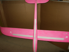
I discovered that when I had check the balance with things dry fit and taped together, I had underestimated the weight of the prop and spinner. I probably should have added the steel balls to the tail. I ended up using about 1.5 oz of lead on the tail to get it to balance. I slide small flat pieces of lead into some heat shrink and shrunk it down. I then glued the lead filled heat shrink tubing to both sides of the horizontal stabilizer with a drop or two of CA.
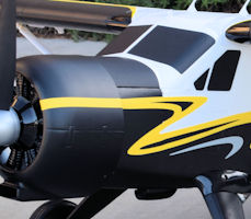
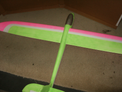
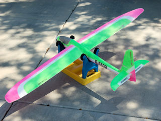
As you can see in the pictures, I chose to paint the model. Rather than discuss that here, look for a separate article on painting.