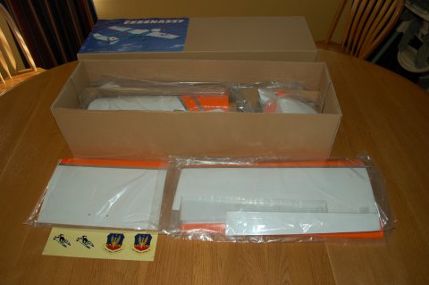
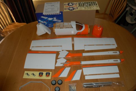
The Nitro Planes Cessna 337 is an ARF. I'm working on the twin .25 version. For a bunch of you who might look at this there is likely a bunch of "so-what" as you've been doing these kinds of models for years.I'm coming from several years of flying mostly foam and mostly Multiplex models.
I figured it's time to branch out. There are a couple of threads on the 337 but most discuss the larger version. I'll also be using electric power.
 |
 |
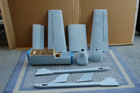
The first thing I noticed about this model is that the instructions assumed I knew a bunch more about balsa models than I actually do.A couple of pictures and almost no words.Jeeze.Off to the forums to see what I can learn. The other thing I did was download and print an assembly manual from a totally different model.While no help on the specifics, it had a lot of good information regarding servo mounting and other assembly tips that the 337's manual simply doesn't address. Much of this log will be consolidating what I found and how I put it to use.
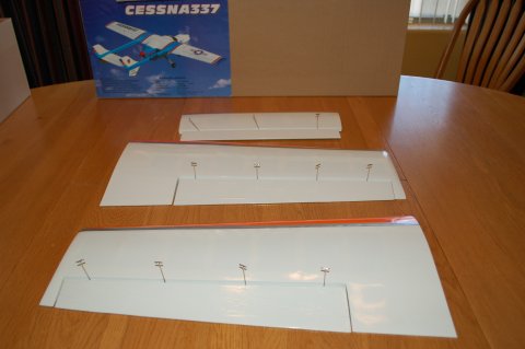
So far the forums have been pretty helpful with lots of folks building and commenting on a variety of issue associated with their models.The 337 came with white and orange trim scheme.The covering was OK but was going to take some shrinking. Oh, wait, no covering tools. Off to the hobby shop.
Hinging and painting
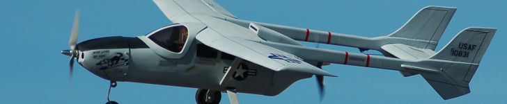
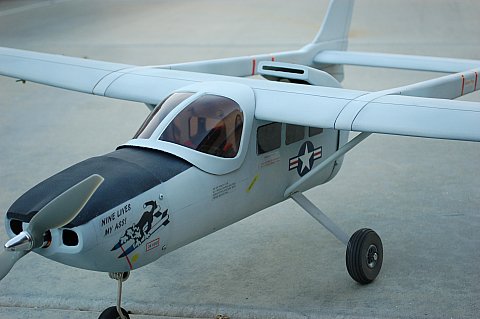
The trim didn't match the photo on the web site or the box.That was OK as I was planning on an Air Force O-2 look anyway. Once the covering was tightened up a little it was going to be painted.The Top Flight Monokote site had some tutorials (http://www.monokote.com/index.html) and there were pointers in several of the forums. The plan I mapped out was to dull the surface of the covering with some 0000 steel wool and wipe and vacuum the surface clean.Next, I've got some Krylon gray primer that made up the first coat. A second coat of dove gray water-based acrylic came next. Usually about half paint and half Windex thins it for my airbrush.
I hinged the control surfaces before painting.I found a nice tutorial here and a cool video here to help explain the process.
The hinging and painting went pretty well. I used the techniques in the video and the controls are on tight. The Krylon stuck and left a flat covering the dove gray stuck to. Both paints were done in multiple light coats.One thing about being in Phoenix, the paint doesn't take long to dry.Before painting I removed the covering over the servo bays and opened the various holes that were covered over.I was afraid the extra thickness of the paint would make them hard to find later.I also masked the servo bays, horizontal stabilizer sockets and inside the cabin area. Two cans of Krylon and one 99 cent bottle of the acrylic craft paint and I was done.Servos, clevises and servo extensions are next.
 |
 |
Servos and controls
I am using Hitec HS-55 servos for the elevator.The elevator on the 337 is controlled by two servos, one on each boom.One is mounted on the inside face and the other on the bottom. The supplied control horns are screwed into place.I'm using Turnigy 1160 servos for the ailerons and nose wheel steering. The elevator servos fit nicely in the pockets.Before placing them I placed 15 CM servo extensions to reach the opening near the wing root.I'm planning on using a Y connector from the receiver to control both servos from the elevator.I went through the same process for the ailerons.Here there were a couple of new things for me.First the model came with pull cords installed in the wings so I didn't have to fish the leads through the wing structure.Second the servo bay assumed 4 mounting screws so there was a gap along one edge of the bay.The Turnigy servos had two centrally located screw hole on the mounting tabs so one end of the servo didn't have much "bite" for the screw.I reinforced that end with some hot glue.I'm using the push rods that came with clevises attached for the ailerons and the third one for the nose wheel steering.Not sure if that is right but the photo shows wire to the elevators.I think they may have been intended for the throttle servo but since this is going to be electric powered I won't need them. I also plan to use quick connects on the servo horns to make adjusting trim easier. One of the little annoyances at this point was the instructions showed the control horns going on with a screw that went through the control surface and into a triangular cap that came attached to the control horn. There were screws of various lengths and I had a couple of false starts on finding the right ones to go through the control surface.After carefully positioning the control horns over the hinge line, I marked the holes with a pencil and used a small thumb drill to make the holes.Someone suggested hardening the holes with thin CA before mounting.I did that and mounted the horns with the small bolts after the CA had cured.
 |
 |
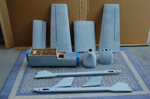
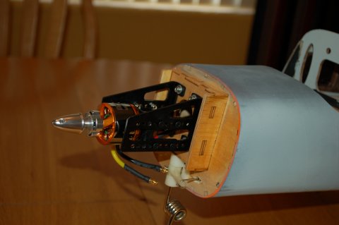
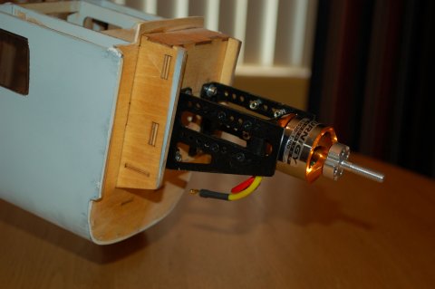
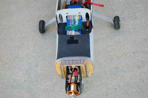
Now the motors
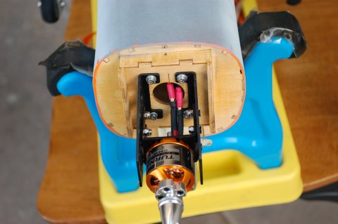
On to the motors.I'm using Turnigy 3536B 1300 kV motors.They say they are equivalent to a .25 to .30 glow motor.With two of them, I'm hoping for nice scale-like performance.We'll see.I ordered the motors from Hobby King along with some batteries and motor mounts. They've been sitting the garage so it's time to put them to work.First I mounted the motors to the motor mount.I decided I wanted to us the bolt on adapter that came with the motors. That meant I needed the motor forward (rearward in the back) of the attachment plate.I placed the cowlings on the fuselage and used a wire to measure the distance from the mounted box to the opening.I marked out the distance on my work surface and set the motor mount length to match. I then placed the fuselage on end and set the motor and mount on the mounting box.I gently maneuvered the mount assembly to center the prop adapter as it exited the hole. After carefully removed the cowl while still on end and held the motor mount down while marking the screw holes.This took several attempts as the mount moved a couple of times when I removed the cowl or I discovered it was sitting a few degrees off perpendicular to the edges of the mounting box.
I hadn't used blind nuts before and experimented a little with positioning them. I found the easiest way for me to get them set in their holes was to place a loop of painters tape on my little finger and stick the nut on it so I could insert it into the box and maneuver it to the hole without dropping it. I could then set it with the screw and I puta drop of CA around the edge with a T- pin to help keep it in place. Access to the rear motor was easier so the tape wasn't necessary. Now on to the tail booms and wing assembly.
 |
 |
 |
 |
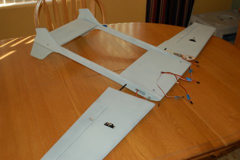
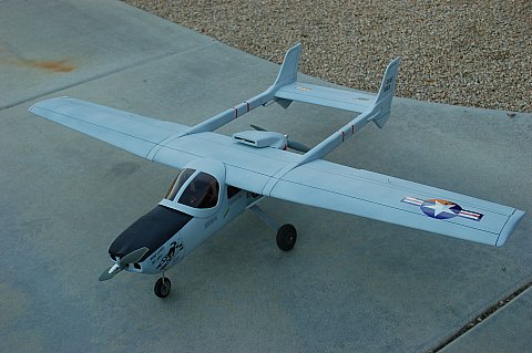
Wings and booms
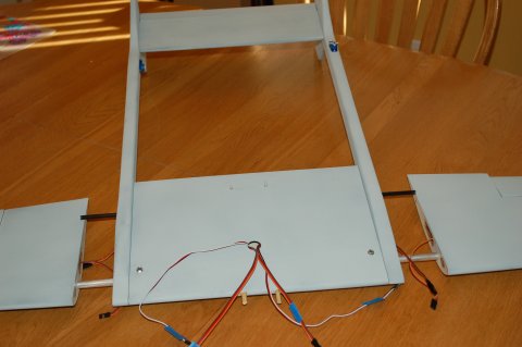
The tail booms and wing assembly worked pretty well.I had used long servo extensions on the elevator servos and snaked them through the tail boom. The plan is to connect them with a y-adapter inside the fuselage and connect it to the elevator channel.I used the string in the center wing panel to pull the servos through that part of the wing.I also pulled another piece of string along as I needed to pull a 12 inch servo extension through to connect with the aileron servos in the outer wing panels.
The wing spars presented a decision for me.I'd read where somefolks slipped the outer wing onto the spar and simply held it in place with plastic tape. The parts fit together tightly and you don't expect a lot of inside to outside force on the wing.Since I had painted the model though, I didn't want to peel the paint.I discussed several ideas with others and decided to drill a small hole through the wing and spar housing and into the aluminum spar itself and place a self-taping screw into both the center panel and the outside panel to secure the wing to the spar.That operation went smoothly though I need to get a couple of slightly longer screws.
 |
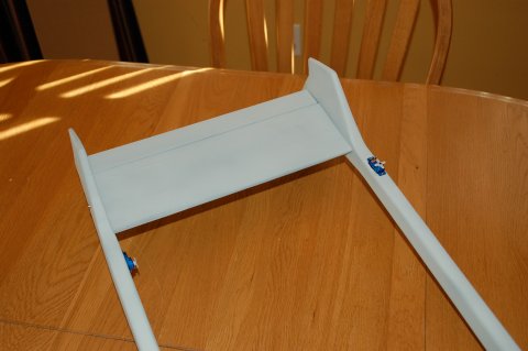
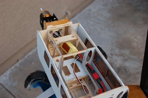
Wiring
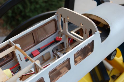
On to the electronics. I wrestled with where to put the ESCs. I had gotten them from BP Hobbies.I'm using inexpensive 45 amp models with no BEC. I considered the motor mounts but chose to go in the cabin of the 337.I soldered the bullet connectors to the ESC and connected the motors.That gave me enough length to get into the rear cabin. I also added a Dean's connector to the ESC.I did the same thing to the front ESC.That one kind of hangs in the space under the front hood of the model. I need to get something in there to secure it. I purchased a dual ESC power y-cord from MPI (Maxx Products). It is just like one you might use to connect batteries, but the connector genders are swapped. I also inserted an MPI arming plug into the circuit.I use one of these on another bigger electric and like it. This plug-type switch allows you to get the battery in the model and have everything assembled before going out to the flight line without having the circuit "hot."When the plug is inserted the circuit is closed and the model powers up.In this case I mounted it under the windscreenI also plan on loading the battery through the windscreen, too.I have the light weight receiver switches in several of my smaller models to switch things off.I just feel safer with the arming plug with more powerful models. When using a UBEC the ESC is still getting power and often beeping signifying a lack of receiver input (when turned off with the smaller switches). Ultimately, if the ESC is hot, so is the motor.Thus my preference for a cold circuit. .I decided to mount the windscreen with velcro. I have a larger pieces, about 1 inch by 3/4 inch along both the leading and trailing edge of the windscreen.I also mounted two small tabs near the lower aft corners.Hopefully it will remain secure. I plan on using a tip from a magazine to use a plastic coated playing card to slide between the hooks and loops to separate them when removing the windscreen.
 |
 |
 |
 |
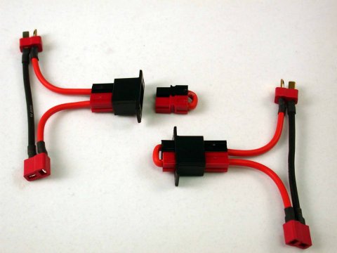
One of the other items I ordered from MPI was some EZ soldering couplers.I hate soldering Dean's connectors.These little jewels allow a solder joint to the wire with something like the well in a bullet connector with the top open and a split tube that slides over the tab on the Dean's plug. Both ends are easy to solder with no globs or cold joints.The heat shrink slides on smoothly too.Very cool.
Radio
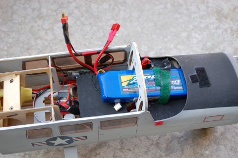
Next I mounted the receiver. I used a 7-channel Spektrum I had. The main receiver went on the model's rear floor deck and the satellite went on the sidewall so the antennas were perpendicular to each other. This model requires two servo Y-harnesses. One goes to the ESCs and the other to the two elevator servos. Each aileron is on its own channel. I made an extension from the arming plug to the battery so I had some length to play with. I put Dean's on both ends.Neither ESC I'm using has a BEC so I wired the UBEC to the extension. I also placed a piece of light ply with a couple of layers of depron foam across the cockpit to form a deck for the battery. I used a velcro cable tie around the square panel cut from the front area under the windscreen to secure the 4000mAh 3-cell battery I'm planning to use.I'm thinking I'll secure the panel with a small screw and washer as I'll seldom need access through it after the battery extension is put in place.
The decals were not difficult to make. The I plan to use one of the two large roundels that came with the model along with some danger arrows and missile decals. I also had some smaller roundels for the fuselage sides.The rest I made using Power Point. I ran them through the my Canon inkjet printer and was a little disappointed in the results. The black had a crackle finish to them. I ordered some fresh decal paper from decalpaper.com. It is about half the cost of Testor's paper from Tower Hobbies.Google images is the source for most of the markings.I printed up a Rescue arrow, emergency exit instructions, servicing statement, tail numbers and prop warnings similar to ones found on actual O-2s.I'm not try for scale perfection but I like to have semi-realistic look.
I also planned on some panel lines here and there.I used some pencils and a Sharpie.The entire plane will get a coat of WBP to seal both the lines and the decals. As mentioned above, the plane sits distinctly nose high. All the wheels are the same size so I added larger main wheels. I had some 2 1/4 inch wheels which helped -- but not enough.Another trip to the LHS.Got some Dubro 3 inchers.They don't look bad and the plane sits much more level.
In studying the pictures I printed from Google images, I finally identified what two unmarked pieces in the kit were.I've been wracking my brain to figure them out.On one image I noticed there was a horizontal vain on each tail boom near the aft end.That has got to be it!
 |
 |
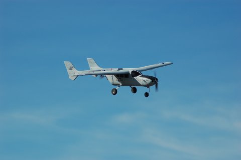
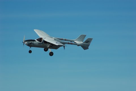
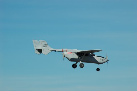
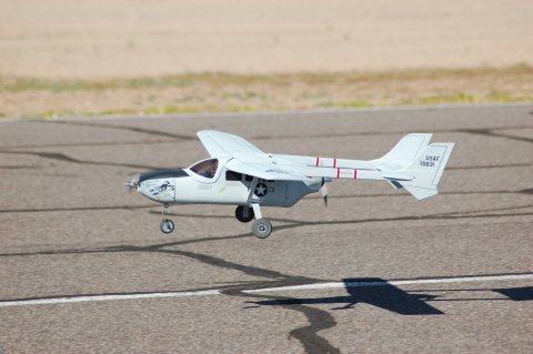
Propping and testing
I debated with myself on the props for this thing.Not sure why, but I had been thinking about 7X5s. When I put one on it was clear that it was too small. They barely cleared the cowling.APC had both 9X6 thin electrics in normal and pusher versions. That is what I went with. My final purchase was some larger rear wheels mentioned above.I could bend the nose gear support back some more, but the metal seems brittle so I'm a little afraid of doing that.I think the larger wheels is a better approach. The three inch diameter Dubro wheels helped the attitude and don't look too much out of place.
As noted above, the rear cowl fit really tight.When I did the final assembly I found the prop scraped the cowl.Either the cowl needed to on further or the motor needed to go out.As you can see on the motor pictures above, the support for the air scoop part of the rear cowl was solid.No air would go into the motor area.Grabbed my rotary tool and sanding drum and fixed a couple of things.First I sanded the center section of the air scoop brace so there were just two tabs.Now the air scoop actually scooped!Next I ground down the top edge of the cowling to allow it to move more forward before hitting the wing.The result is a better fit and a prop that clears the rear of the cowling. I left the mounting screws in the rear under the cowling. I don't plan on removing the center section once I get everything completed.
The finishing touch was a light coat of water-based polyurethane, programming my Spektrum DX-7, setting the control throws and putting a watt meter on it. The final setup resulted in putting about 15 ounces of lead in the nose to get it to balance with a 4000mAh 3 cell battery. The final measurements were:
| Weight: | 5 pounds 10 oz with battery |
| Power: | 576 Watts |
| Amps: | 57 |
| Battery: | 4000 mAh 11.1 Lipo |
 |
 |
 |
 |

![]()